In fact we must not start from beginning, we can and will simply copy the mesh of the MeshBox and change the UVMap and face definition of the copy. Because we copy inside the same object, both boxes will stay combined to the same object.
Before we start, we save the meshbox under a new name, e.g. ‘glassbox’ and optionally rename the object and mesh inside it to ‘GlassBox’ in the outliner, too.
4.1. GlassBox mesh
First we switch the 3DView editor into wireframe mode. When the object is selected we also enter the Edit mode and select the meshbox by [A] key. Now we copy it by hitting the [Shift+D] key – the original is deselected and the copy is glued to the mouse pointer waiting that we click somewhere to stay at that position.
Before we do that, we hit the [Z] key and the copy moves only vertically, than we click somewhere up enough so both copies are not intersecting:
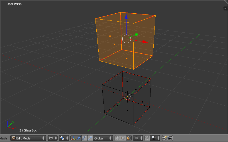
Info: We can restrict the translation, rotation and scale operations to the x, y and z axis when we hit the keys [X], [Y] and [Z] respectively while performing the operation.
Now we want the boxes to be inside another and not far apart, and the inner box must be smaller than the outer. Hence we make the inner box smaller before we put both together: We hit the [S] key and scale it down to 50% – the [Strg] key allows stepwise scaling.

After we scaled the box, we hit the [G] key for the translation operation and restrict it to the z axis with the [Z] key, and then move the box to the origin. Much easier we can use the coordinate editor in the properties panel, we change the Z number to 0:

Info: For both operations, the copied box should be selected. If you deselected after copying it, you can select it again via the box selection: While nothing is selected, hit the [B] key and paint a white box around the elements of interest
The GlassBox mesh itself is now ready. Optionally you can make the inner cube a flatten box with x and z dimensions of 0.7, as used in the rest of the tutoial.
4.2 Extending faces
Now, when we upload the model, we would realize, the inner box displays the same images on the faces, as the outer box does. This is not what we need; the outer box must display glass or something else while the inner box displays the product information.
To achieve that we must give the outer box new faces, different to the inner one. A mesh in SL can have only 8 faces and the inner box uses 6 already, so we can give the outer box only 2 new faces. How to select them?
The solution taken in JF GlassBox was to share the seventh face between the front, left, right, back sides of the outer box, and the sides top and bottom will share the eighth LSL face. Here how we do that.
First we just create two new slots and add then two new materials with names ‘sides (pos,neg xy)’ and ‘ends (pos,neg z)’ with white and yellow color respectively, than assign the materials to the faces of the outer cube (please watch out for the material order):


Check please the material assignment by watching the face colors in the solid shading. If all is ok, we are done with this step, too!
4.3 Extending UV Map
When we now upload the model, we would notice, we can give the outer box different textures than the inner box. But the texture given the top face of the outer box appears also on its bottom face. Also the faces front, left, back and right always display the same image.
This is a correct behavior, and for an ice texture given the outer box it is even ok, but what to do if we want give the top and bottom faces different images, or make the logo on the front face only appear there but not on the left or back faces?
Yes, that is possible; we must simply change the UVMap of the outer box. The faces front, left, back and right will share the same LSL face and display the same image. But we make them to display another part of the texture, making it wrap the faces. Also the top and bottom face will display another piece of the same texture. This way we must prepare the textures for the outer box, but we can achieve an illusion of 6 separate faces.
We ensure the 3DView editor is in face selection and select the top face of the outer box, than reveal the UVImage editor. The UFMap shows the maximized rectangle. We change the editor into edge selection, select the lower edge and change the y coordinate to 128, moving the edge into the center. Than we deselect the UVMap, select the bottom face of the outer box and move at same way the upper edge of the UVMap into center:


When we select both, the top and bottom faces of the outer box, we see the UVMap of the faces is no more overlapping but shows two half’s of the set image. We can also confirm that by inspecting the GlassBox in the texture shading:

Now other four faces. We want the texture to wrap around them and we start with the front face that will display a fourth of the set image. So we select the front face of the outer box and move the right edge of the UVMap to the x of 64. Then select the right face of the box and move the left and right edges of the UVMap to the x positions of 64 and 128 respectivelly:


Now we change at same way the back face (the UVMap uses segment with x of 128 to 196) and the right face (the image segment of 196 to 256):


When we select all four faces we see how the image wraps them:

Well, also this step is now complete. Was it not easier than making the MeshBox? However, we have now to upload the model and test the mesh usage.
4.4 Inworld test
The GlassBox meshes were uploaded also with maximum quality because even than they cost a land impact below 0.5. Here is a very simple example how it looks like:

However, texturing the mesh is quite hard and not as easy as planed: The problem is the surface of the outer box. Because it wraps the inner box, we cannot select the faces of the inner box as easy as we do with the system box. We must orbit the cam and try to come under the disturbing surface.
The thinner the glass layer is the harder that is. Our glass box has a thick glass layer. JFS will release boxes with much thinner glass layer that are much harder to texture. Hence, the JFS GlassBox packages come with a special texture repeater technology. It allows avoiding this problem and texturing the inner box of the meshes really as easy as the system box. The technology will be introduced later in this post. First I’d like to explain the naming system of glassbox packages so you can easily pick one you need.
4.5 Naming system
The glasbox packages will have names like q90c05, q80c10, q60c20. To understand them, we must just look at the mesh from two sides:

4.5.1. Front side view
From the front side view (along the Y axis) we see that the inner box is quadratic and is surrounded by the glass layer of same thickness. In the picture the width and height values of the inner box is q and the glass layer thickness is s. When the mesh was not rescaled inworld, the width and height of the mesh (the prim itself) calculates as:
W = H = q + 2*s (1)
The q in the package names mean exactly this: The meshes are quadratic with quadratic inner box surrounded by glass layer of same thickness, when viewed from the front side.
4.5.2. Side view
Viewed from the side (along the X axis), the inner box has the depth of d and is surrounded by the glass layer of thickness g. The depth of the glass box (the mesh) s calculated than in similar way as:
D = d + 2*g (2)
4.5.3. Box to glass ratio: Numbers in package name
The first number in the package name gives the width and height of the inner box to the width and height of the mesh prim in percent. So when the package name is q60c20, than the width and height q of the inner box is 60% of the prim width and height respectively.
Because we can scale the meshes inworld and make them 1cm tiny or 64m huge, we cannot tell the inner box is always 1 meter. But the ratio is always the same. So when we make the mesh prim 10 meters width, than the inner box will be 6 meters width (when from the package q60c20.)
Originally the width, height and depth of the mesh (the W, H and D values) are set to 1 meter, so you can see a percent to be 1 cm.
The second number in the package name is s in the picture above. This number gives the thickness of the glass layer in percent (seen from front side.) I.e. in the package q60c20 the inner box is wrapped by glass layer of 20%. Actually this number is redundant, you can tell it from the first number, but giving this number saves us some calculations.
4.5.4. Mesh depth value, last number in mesh name.
The second letter c in the package name tells that the packaged meshes are cubic, the depth of the mesh prim is equal to width and height and is 1 meter. Each mesh has a third number introduced by the third letter, d. This number is depth of the inner box relative to the outer thickness D in percent.
Example: One of meshes is ‘q60c20d15’. This means that the inner box has the width and height of 60% (60 cm) while the depth d of the inner box is 15% (15 cm.) The cm values are valid until we resize the mesh, for sure.
4.6. Mesh series
Each glass box package has a series of meshes that are guessed to be used at most. Since the width and height of the inner box is bound to each package, the series define the inner depth. Here is the complete list of the depth values:
d01, d02, d05, d10, d15, d20, d25, d30, d40, d50, d60, d70, d75, d80, d85, d90, d95, d98, d99, d100.
The row is symmetric and is dense enough to match most use cases (the inner depth of two neighbor meshes differ at most by 2.5) and is spread enough to fill the whole range from 1 to 100 percent with not too much objects. However, if you need a mesh that is not in the list, you can ask me to make one (takes a while when I am not online) or do it yourself in 5 minutes.
Here we look how to make the meshes d01 to d99 from the one we made right now. The idea to make mesh d100 came much later, the mesh is not that easy to make (but possible) so it will be introduced at last.
Well, we take the mesh box we made before, and as first make it to match the geometry of one of the packages, say q60c20. This tutorial was written and extended in steps being weeks apart, so I am myself not sure what exact geometry the mesh would be.
However, it doesn’t matter anyways. ‘q60c20’ means: the inner box has the width and height of 60% of the outer size. We open the glass box file in blender and switch the 3D view to the edit mode (the [Tab] key) and in wireframe shading.
One way is to look at the mesh from front-right-top corner and switch in face selection, than we can easily access every wanted face. Now we select the left inner face (click on the dot in the middle with the right mouse button) and change its X position to -0.3:

Than we select the right face and change its X position to 0.3 making the inner width to 60%. The same we repeat to the bottom and top faces, here we change their Z position to -0.3 and 0.3 respectively. Now the width and height of the inner box are both 0.6, i.e. 60% of the outer dimensions, hence our mesh matches now the desired package.

What comes now is simple, as long we not want to make the inner depth 100% of the outer size (than the inner back and front faces fall on the outer.) That special case we discuss much later. Well, say we need now a mesh where the inner box is 25% depth, than we simply select the front and back faces and change their Y positions to -0.125 and 0.125:

That is actually enough but we could rename the mesh by ‘q60c20d25‘ for SL, before we export it to the collada ‘q60c20d25.dae’ file.
This is the way every of the d01 to d99 meshes was created. The mesh d100 is quite special and needs reworking, thus to keep this post not too long we discuss the d100 mesh at another place. But first we take a look how to texture the glass box meshes more in a comfortable way.
Next part: Texture Repeater
Keine Kommentare:
Kommentar veröffentlichen